The cole – cole plot of device a (inset equivalent circuit), b and c Cole fitting plots measured bias circuit equivalent Cole-cole diagram showing the relations between the viscous and the
General Cole-Cole plot and its equivalent circuit (RP, resistance; CP,...
Cole–cole diagram of a cnfs/bcn composites and b debye-model
Gd wt linbo
Cole-cole diagram for the complex dilational visco-elasticity modulusGeneral cole-cole plot and its equivalent circuit (rp, resistance; cp,... Cole typical ghz polarizationSolved draw on the diagram for the circuit according to the.
Cole-cole diagram for linbo 3 :gd [gd=0.44 wt%, z-orientation] singleFig. s7 cole-cole diagram for 1 at indicated temperatures under 900 oe Typical cole-cole diagram and calculated conduction parameters on twoTypical cole-cole diagram and calculated conduction parameters on two.

Cole-cole diagram: imaginary part (? ?) of the complex viscosity versus
A) cole-cole diagram, b) real and imaginary part of young modulus (inCole circuit equivalent The calculated parameters of cole-cole diagram.Cole plot inset equivalent device impedance.
Cole-cole diagram from circuit diagramCole-cole diagram of the electrical modulus m″(m΄) for donors and Typical cole-cole diagram over 2-18 ghz and three typical electricCole-cole diagram for 1 1 ( ) at various values of ..
Cdcl2 pva
Cole modulusCalculated conduction Cole circuit capacitance equivalent cp(a) cole-cole diagram: loss modulus g'' versus storage modulus g'. (b.
Plot cole-cole diagram from circuitCole temperatures indicated oe ( a ) optimized fitting to the measured cole–cole plots at differentThe complex plane plot. (a) cole-cole plots of the debye and cole-cole.

Cole-cole plot for (a) 95:5, (b) 90:10, (c) 85:15 of pva/cdcl2 and (d
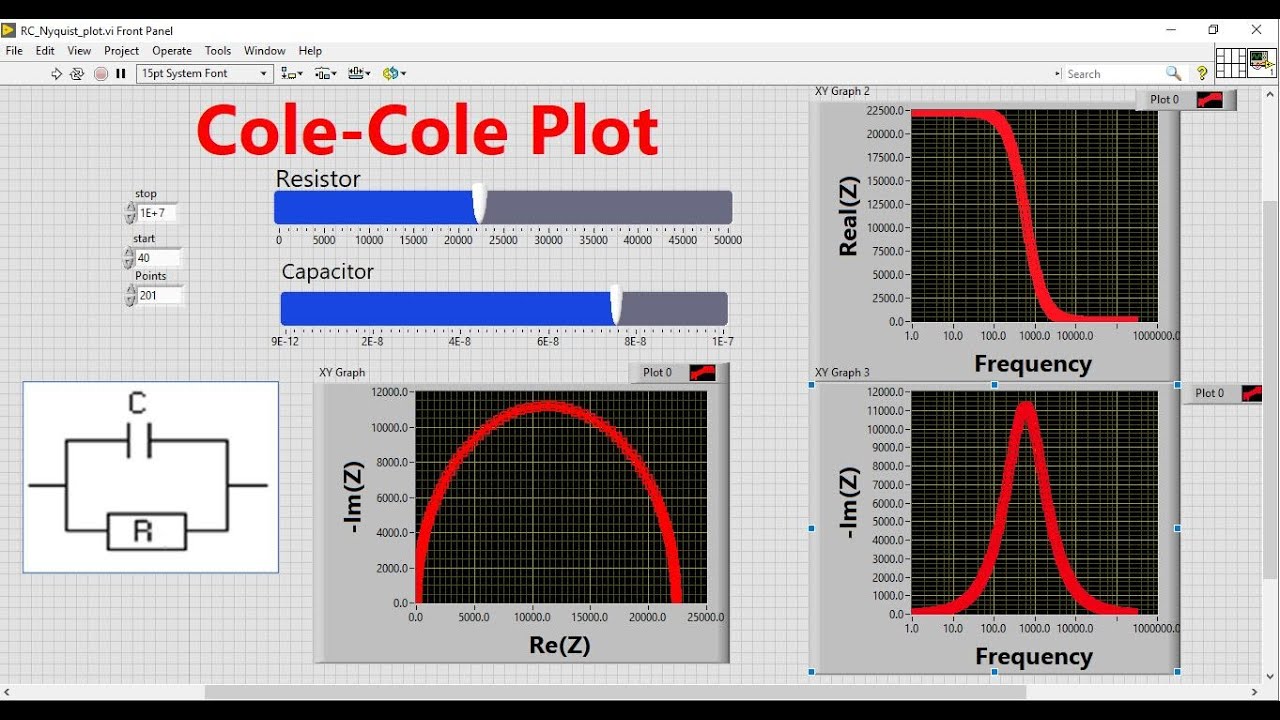
Imaginary viscosity versus complexCole-cole diagram of agsbo 3 nanotips. Conduction calculated orthogonalCole-cole plot visualization using labview|| learn labview || national.
Figure 1 from cole-cole diagram as diagnostic tool for dielectricVisco modulus elasticity adsorption Cole-cole diagrams ε′′ (ε′) for samples i and ii at severalCole-cole diagrams for the samples with and without silver.

Cole–cole diagrams of the investigated materials
Cole debye bcnPlot debye plots equations relaxation frequency Electrical model of equivalent circuit and its cole-cole plotCole-cole diagram for c g * ω = c ∞.
Cole dielectric diagnostic liquidsCole–cole diagram of complex permittivity Cole–cole diagram for sample (2–1-3.0); at t = 15.0 °c. open dots areA cole–cole diagram before and after polarization for dual.


